No products in the cart.
In this blog, you’ll understand what clocking is and how to set it up when configuring interfaces, preamps, and other external audio devices. We’ve also included a glossary so you can get familiar with the connections and how they work.

Basics of Clocking
When digital audio is being transferred between equipment, the receiving device needs to know when each new sample is due to arrive, and it needs to receive a word clock to do that. Most interface formats, such as AES3, S/PDIF and ADAT, carry an embedded word-clock signal within the digital data, and usually that’s sufficient to allow the receiving device to ‘slave’ to the source device and interpret the data correctly.
Clock
clock works by sending an electrical pulse to let each device know when a sample occurs during A/D and D/A conversion. For example, if the sample rate is 48kHz, a pulse is sent 48,000 times per second to let each device know when the samples occur.
- Clock information only travels one way: Master (host) to Slave (expansion).
- Word clock is a square wave that only contains timing information, not audio.
- If synced improperly, the devices may cause pops and clicks or may not even connect.
- Use a master clock to prevent the occurrence of jitter in multiple daisy-chained devices.

Master Device
An orchestra can only have one conductor if you want everyone to play in time together and, in the same way, a digital system can only have one master clock device. Everything else must slave to that clock. The master device is typically the main A-D converter in most systems, which often means the computer’s audio interface, but in large and complex systems it might be a dedicated master clock device instead.
Setting up and synchronize audio devices
Connecting audio devices together digitally is a two-step process. Once the interconnect cables are connected, you need to address syncing them together. Some devices have sample rate and sync source buttons. However, you may need to launch the interface’s control software (e.g., Universal Control, Focusrite Control) to change the sync source (clock source) and sample rate to the appropriate settings.
When setting the clock source, connect the Digital OUT of the Master device to the Digital IN of the Slave device. Also, make sure that the Masterdevice is set to INTERNAL and the Slavedevice is set to EXTERNAL, sourced by whichever clock connection you’re using (ADAT, S/PDIF, WORD CLOCK). Refer to the user guide of your interface for specific setup instructions.
Connection 1:Example 1: Adding additional inputs to an interface (ADAT)
If you have a mic preamp, like a Focusrite OctoPre, you can connect it to your interface via ADAT to expand your I/O(if your interface supports expansion).
This example shows how to connect a preamp to an interface to add additional inputs. The setup is a bit different than others because you must set the preamp as the Master device. If you want to add additional outputs, see Example 2 below to create an ADAT loop.
- Connect a TOSlink cable from the ADAT/Optical OUTPUT of the preamp to the ADAT/Optical INPUTof the interface.
- Set the preamp as the Master (Internal) and the interface as the Slave (ADAT).

Example 2: Adding additional inputs and outputs to an interface (ADAT)
This example shows how to add additional inputs and outputs by creating an ADAT loop. Unlike the previous connection, you can set either the preamp or interface as the Master, but it’s recommended to choose the device with the better clocking technology. As long as one device is configured to ADAT and the other is configured as Internal, you won’t run into any issues because they’re synchronized.
- Connect a TOSlink cable from the ADAT/Optical OUTPUT of the preamp to the ADAT/Optical INPUT of the interface.
- Connect a TOSlink cable from the ADAT/Optical OUTPUT of the interface to the ADAT/Optical INPUT of the preamp.
- Select either the interface or the preamp as the Master (Internal) and the other as the Slave (ADAT).

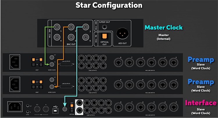
Example 3: Syncing using an external master clock generator (Star configuration)
If you have multiple devices you need to sync via word clock, you can use an external master clock generator. These are extremely useful, especially when clocking three or more devices or when video equipment is involved.
- Connect a BNC cable from the OUTPUT of the external master clock to the INPUT of the Slave devices.
- Set the external master clock to Master (Internal) and all other units to Slave (Word Clock).

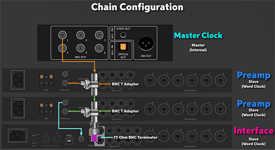
Example 4: Syncing using an external master clock generator (Chain configuration)
- Connect a BNC cable from the OUTPUT of the external master clock to one end of a BNC T-adapter.
- Connect the BNC T-adapter to the Word Clock IN of the next device.
- Connect a BNC cable from the other end of the T-adapter to the end of the next T-adapter in the chain.
- Once your chain is completed, us a 75 Ohm BNC terminator on the very last T-adapter.

Types of Digital Converters
ADAT
ADAT (Alesis Digital Audio Tape) connections are used to expand the number of inputs and outputs of your external devices. They use an optical TOSlink (lightpipe) cable and add up to eight additional 24-bit 48kHz audio channels, depending on the sample rate.
- Most TOSlink cables have a protective plastic cap on the tip. Be sure to remove it before making your connections.
- ADAT outputs are commonly used to connect to external devices like headphone distribution systems and D/A converters.
- The sample rate used will determine the number of channels in which audio is transmitted.
- 44.1kHz or 48kHz: Eight channels
- 88.2kHz or 96kHz: Four channels
- 176.4kHz or 192kHz: Two channels
BNC
BNC connections are another way of sending the digital clock signal. One advantage of BNC over other digital connections is that it’s easier to sync multiple devices using a dedicated master clock.
- If connecting more than two devices via BNC, be sure to use a T-adapter throughout your chain.
- You must use a 75-ohm coaxial cable. Consumer-level coaxial cables (commonly used for cable TVs) are only 50 ohms and will not provide the amount of signal required to clock.
- Terminate the last device in your clocking chain, especially with larger setups. Doing this stops the clock signal from bouncing back, which causes connection dropouts.
- Some devices have termination switches, but you may need to invest in a terminator to attach the T-adapter.
AES/EBU
AES/EBU (Audio Engineering Society/European Broadcasting Union) connections are commonly used in professional environments such as live events and broadcasting, especially if there is a large amount of outboard gear and the cable runs are over 30 feet. They use XLR-to-XLR or DB-25 cables to send the digital signal.
- Standard XLR (microphone) cables have an impedance of 75 ohms, lower than an AES/EBU cable, which has an impedance of 110 ohms.
- While you can use standard XLR mic cables in a pinch, you risk noise and interference issues if the cable length is more than approximately 5 feet.
MADI
MADI (Multi-channel Audio Digital Interface) is a form of digital connection similar to ADAT. The sample rate dictates how many channels you can use through a single connection. You can also route each channel independently, making it easier to send the signal to multiple sources. This connection is commonly used in large-production environments such as concerts and broadcasting.
- The sample rate used will determine the number of channels in which audio transmits.
- 24-bit 48kHz: 64 input & output channels
- 24-bit 96kHz: 32 input & output channels
- 24-bit 192kHz: 16 input & output channels
- The maximum cable length depends on which type of MADI cable is used.
- MADI optical cable: 2,000 meters
- MADI coaxial cable (75 ohms, BNC connection): 100 meters
